
There is something magical about pulling high-resolution images of Earth directly from space. While I did start with a QFH Antenna for NOAA satellites, I wanted to go for the “big prize”: GOES-19.
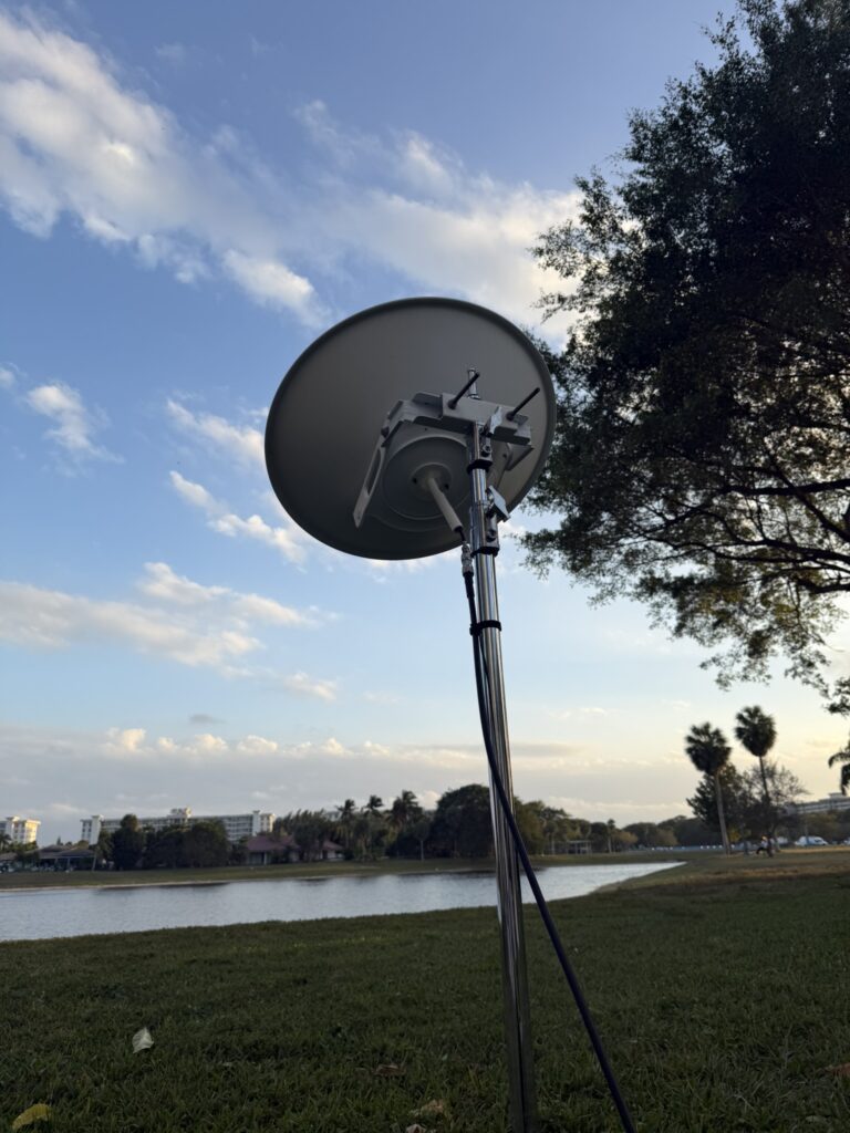
Because GOES satellites are geostationary, you need a high-gain directional setup. Instead of buying a pre-made grid antenna, I decided to “frankenstein” one using an old Ubiquiti AirMAX dish, a 3D-printed mount, and some cheap parts from amazon. Here’s how I did it.
The Gear List
To get a clean signal from 22,000 miles away, you need a solid signal chain. Here is what I used:
You can find all of these products on my Amazon Storefront (minus the dish)!
- The Dish: A repurposed Ubiquiti AirMAX Dish.
- The Brains: RTL-SDR Blog V4 – The gold standard for entry-level SDRs.
- The Muscle: Nooelec SAWbird+ GOES – This is a must-have; it’s a combined LNA and filter that targets the 1688MHz to 1694MHz range.
- The Feed: WA5VJB 2.4GHz Log Periodic Antenna.
- The Cabling: RG-8X Coaxial Cable – Low loss is key at these frequencies.
- The Structure: 1/2″ PVC pipe and a custom 3D-printed center bracket.
The Build Process
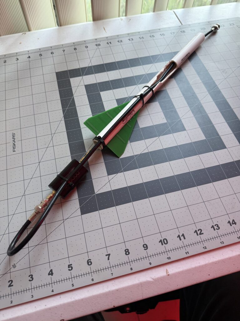
1. The Feed Assembly
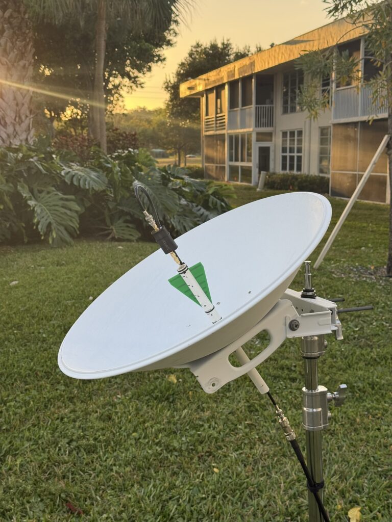
The most critical part of a parabolic antenna is the “feed”—the part that sits at the focal point of the dish. I used a short length of 1/2″ PVC pipe about a foot long. I cut a slit down the top to slide the WA5VJB antenna into place and drilled a hole in the side to route my RG-8X feed line through. Ended up having to extend this hole several times to allow This keeps the antenna perfectly centered.
2. 3D Printed Center Bracket
The original AirMAX feed is designed for 5GHz WiFi, which won’t work for GOES. I designed and printed a custom bracket that bolts into the center of the dish and holds the PVC pipe securely. This allows me to slide the pipe in and out to fine-tune the focal point for maximum “SNR” (Signal-to-Noise Ratio). Unfortunately this isn’t a one size fits all so I’d recommend engineering something that positions the pvc pipe in the center of the dish while giving you the ability to adjust a bit for polarity.
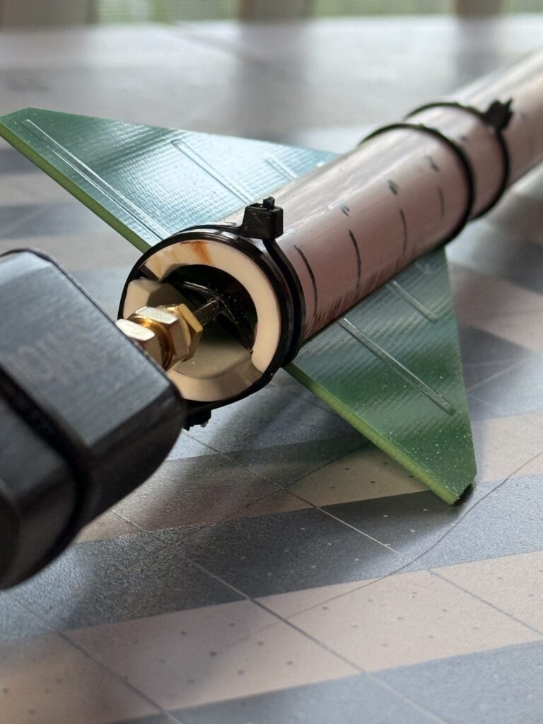
3. The Signal Chain
The wiring is straightforward but important to keep some key factors in mind. The WA5VJB antenna connects directly to the Nooelec SAWbird+. If you connect the sawbird later in the feedline you run the risk of introducing a lot of additional noise from the line instead of just soloing out the antenna.
Note: Make sure you have “Bias-T” enabled on your SDR software to power the SAWbird through the coax!
From the SAWbird, the RG-8X cable runs down to the RTL-SDR Blog V3 plugged into my computer (or a Raspberry Pi running goestools). Adapters and connecters are important to think through. A lot of my connections are BNC to allow for easy connection but the SDR and SAWbird are SMA connectors so I needed an adapter for both ends
Aligning with GOES-19
Since GOES-19 is geostationary, once you find it, you never have to move the dish again. For positioning, I went to https://www.n2yo.com/ to get the azimuth and elevation from my coordinates. I used my phones compass and level to set the dish to the correct general position then watched the “Viterbi” error rate in my software. As I nudged the dish, the error rate dropped, and suddenly… data started flowing.
Final Thoughts
Building your own GOES station is a rewarding mix of radio theory, scavenging, and space studies. Seeing a full-disk image of the Western Hemisphere pop up on your screen for the first time is a feeling you can’t get from just looking at the weather channel.